Offshore Wind Energy

A technology brief on offshore wind turbines that harvest energy from ocean breezes

In This Technology Brief...

What is Wind Energy?

Wind is the result of moving air masses responding to pressure and temperature differences in different locations. Nature is constantly trying to achieve equilibrium. When an air mass is at a higher pressure than air in a different location, the high pressure air will flow to the region that is lower pressure. The larger the differences in pressure, the stronger the wind. 

If you’ve ever spent time on an island, you may have noticed the wind displaying some predictable behaviors. On a sunny day an island and the surrounding seawater will heat at different rates, the water generally lagging behind the land. The land warms faster causing the air directly above it to rise like steam from a pot of boiling water. The rising air creates an area of low pressure in its wake. The air temperature over the water is relatively cooler and at a higher pressure. In an attempt to achieve equilibrium, the air flows from the sea towards land to reduce the pressure difference. This is a sea breeze and the greater the temperature difference the stronger the breeze. At night the reverse can happen as the warm ocean water is now hotter than the land, generating an offshore breeze.

sea breezes diagram
Onshore and Offshore breezes. Source: “Oceanography” 6th Ed. Garrison, T.

A similar effect happens at a global level as well. The Earth’s equator gets significantly more solar heating than the higher latitude bands to the north or south. The warm air at the surface around the equator rises and cooler air from higher latitudes flows in to reduce the pressure difference. This circular mixing of air is what creates our reliable trade winds that sailors have been using for hundreds of years and more recently what we’ve been utilizing to power offshore wind turbines.

global air circulation diagram

A flowing fluid like wind or water contains kinetic energy. This energy can be harvested and converted to useful mechanical or electrical energy using several different technologies. Turbines are by far the most common.  

A turbine is a series of blades attached to a common hub which spin about an axis when acted upon by a fluid with kinetic energy. As wind flows across a turbine’s blades, the wind’s kinetic energy causes the turbine to rotate. If the shaft is connected to an electrical generator it will produce electricity when the turbine rotates.

The blades on a turbine have a unique shape and curvature that resembles a slender teardrop when viewed from the side. This unique shape is called an airfoil (or hydrofoil if its in the water). If you’ve ever been sailing or travelled in an airplane you have seen an airfoil at work in the sail or wings, respectively. These airfoil shaped blades rely on lift or drag to create the spin. 

As air particles flow across an airfoil a low-pressure area develops on one side resulting in a force that acts on the foil in a direction that is perpendicular to the wind’s direction. This force is called lift and its what causes airplanes to fly. There is another force produced by wind flowing over a blade, but which acts in a direction parallel to the wind, which we call drag. Wind turbines can take advantage of either of these forces, but most blade designs try to maximize lift and minimize drag. For a more in-depth discussion on lift, see this article.

airfoil diagram
Air streams along a foil. Source: "A Physical Description of Flight; Revisited" Anderson,D and Eberhardt, S.
airfoil reaction forces
Forces on a blade. Source: "A Physical Description of Flight; Revisited" Anderson,D and Eberhardt, S.

Wind Turbine Basics

exploded view of a turbine rotor and nacelle

The power available to a wind turbine is given by the equation:

P = ½ A ρ V³

In the equation above, P is the power in watts, A is the area swept by the wind turbine in square meters, ρ is the air density in kilograms per cubic meter (around 1.2 kg/m³ for air), and V is the wind speed expressed in meters per second. This equation also applies to tidal turbines.

Notice that power is directly proportional to the cube of the wind velocity. So even a modest increase in the wind speed can have a tremendous effect on the available power. Likewise increasing the size of the turbine can also increase power – since the swept area is proportional to the square of the radius, or turbine blade length, increasing blade length leads to exponential gains in power. 

This equation helps to partially explain two trends with offshore wind. First is the desire to move further offshore where there is cleaner and stronger wind. Second, offshore wind turbines have been trending towards ever bigger designs to maximize on power output. 

One might assume that more wind is always a good thing.  Wrong. Turbines are designed for an optimum range of wind speeds, but beyond that they will cut-out and stop producing power in order to protect the turbines gearing and generator.  So just as too little wind can be a bad thing, so can too much.

 
wind power curve
Typical power output of a wind turbine. Source: https://www.wind-power-program.com/popups/powercurve.htm

The equation above will provide the theoretical maximum power output from a wind turbine. In the real world we must factor how efficient the turbine system is at harvesting the wind. Even with the most efficient turbine, the maximum power that can be extracted from the wind is given 59.3% of the kinetic energy. This is what’s known as the Betz Limit.  Modern offshore wind turbines obtain values that are around 80% of the Betz limit.

Offshore Wind Design Archetypes

Offshore wind turbines are similar to their terrestrial counterparts, but are typically larger. Offshore wind turbines are larger because it pays to go bigger; the wind is more consistent, there are less obstructions, and if a company is going to go to the trouble to install a turbine in the ocean, they’ll want it to generate as much power as possible.

Offshore wind designs can be classified by their foundation type and the turbine design. When it comes to supporting the turbine there are three possibilities: fixed, floating, and airborne. For the turbine the majority of designs you’ll come across are either a variant of a horizontal axis turbine or a vertical axis turbine. Let’s look at each.

Offshore Wind Foundations

different types of bottom mounted wind turbine foundations
Different types of seafloor mounts for offshore wind. Source: “Onshore and Offshore Wind Energy: An Introduction”, Lynn. P.
Most offshore wind turbine foundations use large towers that extend from the turbine to the seafloor and are aptly named ‘bottom mounted’. In these systems the supporting tower is either driven into the seafloor; attached to a large, heavy base on the seafloor; or a multi-legged foundation that resembles a tripod where each leg is drilled into the seafloor.  Keep in mind that a bottom-mounted wind turbine needs a tower that extends the depth of the water and then however high the turbine needs to be for the blades to clear the water. For this reason all of these fixed foundation types are limited to water depths of around 60 meters, beyond which it becomes too difficult and expensive to connect the support tower to the seabed.
floating offshore wind concepts
Different mooring systems for floating wind turbines. Source: Floating Wind Turbine
In water depths beyond 60 meters a turbine must rely on a floating platform. Such systems are generally referred to as floating offshore wind. With floating offshore wind, the turbine tower is mounted atop a semi-submerged platform which is partially sunk, to make it more stable, and tethered to the seafloor. There are a variety of platform designs used for floating offshore wind. A submerged tension-legged platform (TLP) uses taught mooring cables to connect the platform to the sea floor. A spar buoy, which looks like a long pendulum, uses a weighted ballasted tank with a low center of gravity to provide stability. And lastly the tri-float design uses three interconnected pontoons that can be ballasted with water for stability to support the turbine. Floating offshore wind is not as common as fixed foundations, but the platforms themselves are well tested by the oil and gas industry. But not every coastline is graced with shallow water near shore, some regions like the U.S. west coast with deep water close to shore will have to rely on floating offshore wind.
Airborne wind systems lack a support tower and do away with the need for a heavy foundations. In these systems the turbine is held aloft at a high altitude using blimps, kites, or gliders where it can benefit from high velocity and more persistent wind. These systems are the least common and are still technologically immature, but there is potential for them in the offshore industry. The Makani Energy Kite (company was dissolved in 2020) used a kite which glided 800 to 2000 feet above the ground and generated power via several small turbines that were mounted to the kite. Shell expressed interest in the system and it was tested in the North Sea in 2019.

Offshore Wind Turbines

There are two general types of wind turbines commonly used, horizontal-axis wind turbines (HAWTs) and vertical-axis wind turbines (VAWTs). HAWTS and VAWTS are distinguished from one another by the orientation of the turbine shaft, but these turbines can also be differentiated based on whether the turbine uses drag or lift in the blades to turn the rotor, or whether the turbine rotor is facing upwind or downwind. 

A HAWT has its shafts oriented horizontally, parallel to the the ground. These turbines typically have two or three blades, the latter is far more common than the former. A HAWT can have its turbine blades mounted on the upwind or downwind side of the nacelle. If they are mounted on the downwind wind, the turbine will naturally yaw into the wind direction like a weather van, but the turbine will also have reduced wind due to blockage from the nacelle and tower. If the turbine is mounted on the upwind side a mechanical yawing system is needed to orient the turbine into the wind, but the wind hitting the turbine is unobstructed. Upwind models are generally more common than downwind models.
A VAWT has its shaft oriented vertically, perpendicular to the ground. Unlike a HAWT, these turbines don’t need to be yawed into the wind and the power generation equipment can be stored at ground level instead of in a nacelle at top top of the supporting tower making it easier to access. At smaller scales, these designs are more compact than HAWT and are more commonly found in residential areas where space is limited. VAWTs are also said to perform better than HAWTs in gusts or when the wind is highly variable in direction. Some common VAWT variants include the Savonious, Darrieus, H-rotor, and helical designs.

Wind Energy Blog Posts

All energy harvesting technologies have evolved from fixed-bottom to floating systems via two distinct phases, some remarkably quickly.

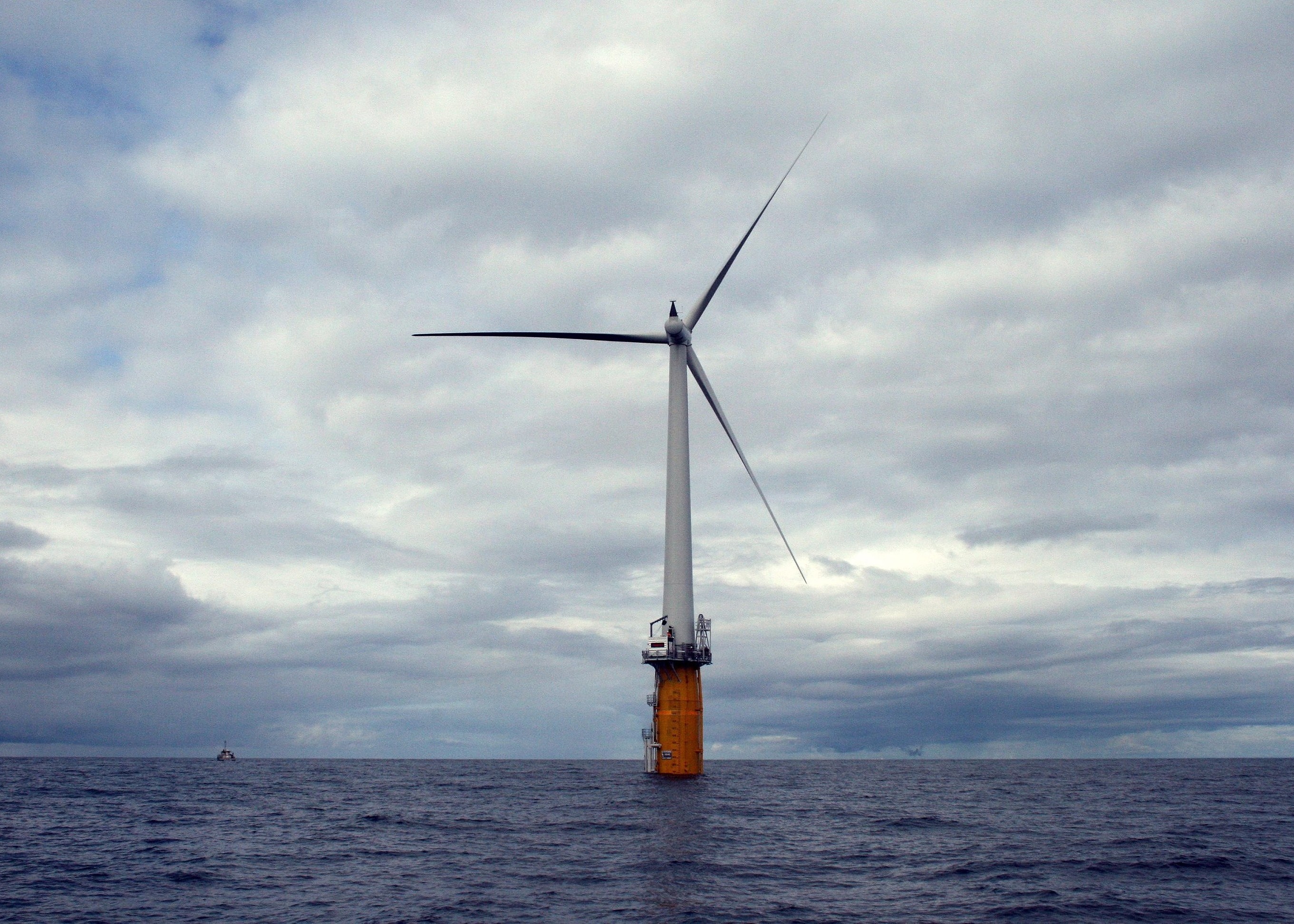
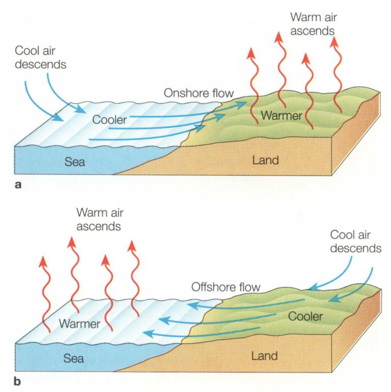
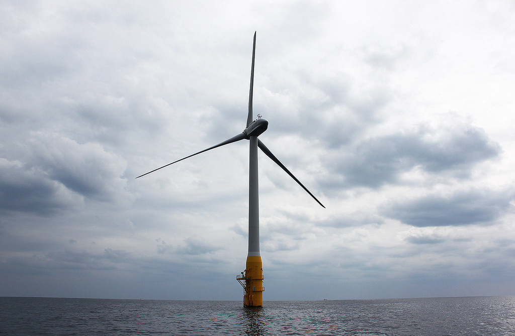
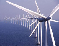
The same winds that carried famous explorers like Magellan or Dora the Explorer away from shore are enjoying a renaissance with the offshore wind energy

Wind Energy Resources

Thanks for subscribing to The Liquid Grid! You’ll receive email updates when new articles are posted.

The Liquid Grid

Learn about the latest in marine clean tech

Subscribe

Your contact information will never be sold or shared with third-parties